

Resistors are common components of most circuit boards. A resistor adds resistance in a circuit.
In this tutorial:
See also:
- Electrical conductors, semiconductors & insulators (coming soon…)
Symbols


Definition
A resistor is a passive two-terminal electrical component that implements electrical resistance in a circuit.
The unit of measurement for resistance is the ohm (Ω).
The tolerance rating of a resistor represents the percent error that the actual resistance can deviate from the stated resistance. [1]
Fixed resistors have resistances that only change slightly with temperature, time or operating voltage. Variable resistors can be used to adjust circuit elements (such as a volume control or a lamp dimmer) or as sensing devices for heat, light, humidity, force, or chemical activity. [2]

Uses
Resistors have many uses, such as:
- Limiting current flow
- Reducing current in circuits
- Suppressing noise
- Adjusting signal levels
- Dividing voltages
- Biasing active elements
- Terminating transmission lines
The fixed resistor in the circuit pictured protects the LED from blowing. The circuit has a 9-volt battery attached, but the LED only requires about 3 volts.
Unlike LED’s, resistors do not have a positive and a negative lead; they can be connected any which way around.
Identifying
This is a little bit confusing at first, and I encourage you to have a system of storing your resistors in such a way that you can easily track the different types. You can buy a compartmentalized storage container from your local DIY or fishing tackle shop.
My The Ultimate Mega 2560 R3 Starter Kit came with this useful sticker.

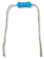
Using the above chart, we will now calculate the specifications (resistance and tolerance) for the resistor pictured below left:

Yellow, purple, black, black, brown
| 1 | 2 | 3 | 4 | 5 |
|---|---|---|---|---|
| Multiplier | Tolerance | |||
| Yellow | Purple | Black | Black | Brown |
| 4 | 7 | 0 | 1Ω | ±1% |
This identifies the resistor as 470Ω with a ±1% tolerance
Ohm’s Law
To understand the relationship between current, voltage and resistance, you will need to take a look at Ohm’s Law, which “states that the electric current through a conductor between two points is directly proportional to the voltage across the two points”. [3]

References:
- Wilderness Labs Developer Portal (no date) Resistor Tolerance and Preferred Values. Available at: https://developer.wildernesslabs.co/Hardware/Tutorials/Electronics/Part4/Resistor_Tolerance/ (Accessed: 3 March 2025).
- Wikipedia. Wikimedia Foundation. (2024) Resistor. Available at: https://en.wikipedia.org/wiki/Resistor (Accessed: 8 July 2024).
- Wikipedia. Wikimedia Foundation. (2024) Ohm’s law. Available at: https://en.wikipedia.org/wiki/Ohm%27s_law (Accessed: 24 February 2025).